
 |
 |
 |
|
 |
 |
 |
|
 |
 |
 |
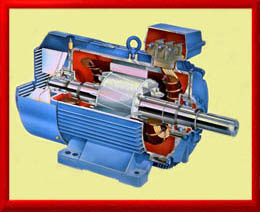
I remember when these first came on the market. I had seen just a mere handful at the Machine Tool show in Chicago in 1982. A 5 horse power drive was the size a small cube refrigerator and cost thousands of dollars back then. Today a 5 HP drive almost fits in the palm of your hand and only costs a few hundred dollars. The heart of these drives are IGBTs (Insulated Gate Bipolar Transistors). This was a new type of semi conductor device that could handle the switching speeds and currents needed to run AC motors. Years ago DC SCR drives were the king of high horsepower variable speed drive systems, but the mechanical brush and commutator systems on these motors wore out fast and resulted in long periods of down time and high maintenance costs. AC motors are brushless and the only thing that wears out are usually just the shaft bearings, which can last a long time if cared for properly.
The problem with AC motors is that their speed is controlled by the line frequency of the current flowing through them and not the voltage. The only way to vary the speed was to vary the frequency. For many years the only way to do this was use variable speed DC motor generator sets, but this was not economical. Then IGBTs appeared on the scene. These transistors are switched on and of at a rate determined by a computer algorithm embedded in the IC chips in the drive. A microprocessor monitors the current and frequency to keep the output optimized for the desired speed.
The output of these drives on an oscilloscope looks like a series of square waves of equal but opposite polarity filled with dozens of odd harmonics. If you added these harmonics together mathematically the sum of the output adds up to a pattern that when graphed resembles that of a sinusoidal wave. This is what the motor windings see. The windings are dumb. They are just plain copper and cannot really tell if the waves are rounded or squared.
The square edge of the waves result in faster transitions when switching polarity and the hysteresis characteristics of the motor windings do not like this after they have been saturated with current in one direction. As a result a regular AC motor runs hotter when hooked up to an AC drive, which over time can result in the breakdown of the varnish insulation on the stator windings.
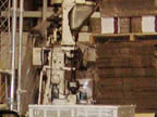
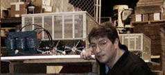
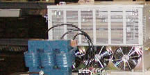
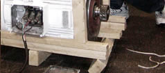
That is why they came out with what are called Inverter Duty Grade AC motors. These motors can handle the faster switching currents without overheating and will last you almost forever when cared for properly. Today AC drives are very common and DC drives are fading into obscurity as AC drives are being enhanced with more and more features and given more capabilities. View the slide show to see the installation of a 125 Horse Power AC Drive by clicking on the yellow box on the left side of the page.