 |
 |
 |
|
 |
 |
 |
|
 |
 |
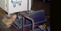 |
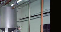
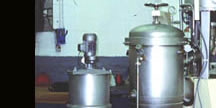
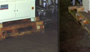
Unbeknownst to me this project turned out to be the real reason I was hired at Union Standard Machinery back in December 1997. When I was first hired to work there as an Industrial Electrician they put me on a couple of little jobs right away to see what kind of work I could do. I was on a 35-day trial period, but I knew I proved my worth beyond all doubts because they fired the chief electrician before my trial period was over. After my 35 days were over, they brought me to a room where the machine you see above was being rebuilt. This is a steam heated Candy Cooking Machine with automatic ingredient pumps, vacuum cooling, and a pressurized whipping chamber used to aerate the candy and whip it into a light fluffy candy substance called nougat.
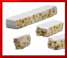
This machine was purchased from Union by a company, which made Italian food products. They made an Italian Candy called Torrone. Torrone is a very simple white colored nougat candy made from egg whites, honey, nuts (usually almonds) and some type of cane sugar. Perhaps you have seen it in candy stores for yourself. It is very popular in Italy, the USA, and many parts of the world.
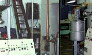
Terbraak of Rotterdam Holland makes this machine. Union Standard bought it at an auction in the Mideast and had it shipped to the USA. The problem was when it got to the US they discovered that the control relay panel had been left behind at the factory where it came from. So all they had here was a machine with no electrical guts or logic to run it. This is where I came into the picture. They did have a schematic and a verbal description of how each aspect of the machine was supposed to function in relationship to the other parts. My job was to take this information and make into a running machine. At the interview I told Union I knew about how to install a program PLCs, and now the time had come. The strategy was for me to wire the machine parts through a PLC and program it to operate in accordance with the original methodologies in a functional description that would be suplied to me.
I had designed a complex electric system for a machine before by using the operation description before, but this was 16 years ago on the Vulcan 6 axis Vertical Boring Mill Project. (See the machine tools section of this web site). Now I was in the hot seat. I had no recent PLC experience and I had just been hired as a PLC expert. What do I do now? I will now show you how I turned this project into a gigantic success starting from the point of near dead zero experience. (One of my favorite starting positions on the job!)
Step 1) All of the elements for the input and output circuits appeared to be present. I laid out the schematics and carefully traced all the wiring from the input and output devices to the main terminal blocks and rewired them to match their factory original configuration. This was very tedious task and it took a lot of time, but I heard that the customer had a Terbraak already and this was to be his second so it was important that I retain the original controls to match what he had already to reduce his training and familiarization costs.
While doing that, after work I would take home PLC brochures and catalogs with me at night and read them to try and become familiar with what was out there. After a few weeks I finally decided to go with a brand called PLC Direct (Now Automation Direct). They had a product line that was very broad and relatively inexpensive compared to others and their documentation was user friendly and easy to understand. I decided to use their model 305 PLC with AC input and output modules along with a timer module with BCD switches so the timer values in the PLC program could be changed by the user without using a laptop computer to reprogram them.
Step 2) After reconstructing the input and output circuits I had become intimately familiar with all the circuits of this machine and I knew how each one worked down to the last detail. I them wired all of the input circuits to the input modules and all of the output circuits to the output modules. Here is where the most important piece of information I had on this project comes into play. This was the functional description of the operation sequences for the machine. There were three modes: Manual, Semi-Automatic, and Automatic. To show some progress to my bosses so they could relax a bit I wrote a Boolean ladder program to facilitate the manual operation of the machine. This program essentially used the software to connect the switches on the front panel to the motors and valves that ran the machine.
Once that was done I added contacts in parallel to the existing manual rungs to facilitate the semi-automatic, and automatic modes of the machine. This I was able to do in stages and test each stage. I started with the ingredient add cycle, then the cook cycle, cool cycle, discharge cycle, whip cycle and dump cycle. I kept on testing and retesting over and over until with one push of the button right before ones eyes the machine would operate on its own according the description from start to finish without human intervention right down to the very last step.
The final test was to have the customer come in and check it out to see if it is what he wanted. The customer arrived early one morning with his technical people. He had a very disgusted looking on his face because the project had been delayed by many months. It took me over 3 months to get my part done. The customer's name was Nick, and I will never forget this moment for as long as I live. He stood in front of the machine and said "O.K. go ahead! Hit it!" I turned it on and switched it auto mode and pressed the start button and the machine began to run perfectly from one step to the next, and as it ran I watched Nicks face switch from a frown to little smile, and then a bigger smile, then a huge grin, until when it was over he was howling with delight! He came over shook my hand and embraced with a hug. He thanked for all I had done. He told me I built a machine that works even better than the one he had now in his plant. The customer was happy and I felt great. All the guys in the shop had heard about how the customer was overwhelmed with happiness over the way this machine had turned out. And from that point forward I was given the nickname COMPUTRON by my fellow workers because they all knew they now had their own in house automation expert who could take on any machine project even if all the guts, and technical manuals are gone. After the machine testing session, Nick accepted the machine and told us to ship it to his factory.
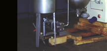
About a year and a half later I was called to Nicks factory to start it up. He had been expanding the factory when he accepted he machine. Now the expansion was done, the machine was installed, and it was time for me to start it up. I had brought the laptop with me with the program just in case because the program was only being stored under the power of a lithium battery in the PLC for a year and a half. I was not sure it would still be there and thought I might have to reload it. The machine powered up perfectly and ran through the automation cycle without a hitch. At that point I decided that Direct Logic PLCs would be the brand I would use for the rest of my life in my design projects, and that has not changed. I still buy their products through their valued added reseller Saddlebrook controls in New Jersey. I have a good rapport with them and they give me great after the sale support.
Since the Terbraak I have gone on and built many more PLC projects but these are of a new type of logic that I call control point splice, which I explain in the PLC section of this web site.